How to fix charge pipe failure on tuned M3/M4
The S55 twin-turbo inline-six engine delivers outstanding performance in the F80 M3 sedan, F82 M4 coupe, and F83 M4 convertible, but the factory charge pipes—constructed from lightweight plastic—become a critical weak link once tuning elevates boost levels. Stock components handle OEM pressures reliably, yet even moderate Stage 1 or 2 tunes pushing 22-28 psi frequently cause splits, cracks, or complete separations at flanges and seams.
Material fatigue accelerates from repeated thermal expansion under turbo heat exceeding 400°F, combined with pressure spikes during aggressive throttle application. Failures often concentrate on the hot-side pipes routing from compressor outlets to the air-to-water intercooler, as these endure peak temperatures and vibrations. Cold-side piping to the throttle body sees fewer issues but can fail in extreme methanol-injected setups. Age and mileage beyond 40,000-60,000 miles compound risks, with tuned examples sometimes experiencing blow-offs within weeks of modification.
Spotting Distinct Indicators of Charge Pipe Compromise
Manifestations range from subtle to catastrophic. A sharp bang or pop under full load signals sudden detachment, followed by drastic power drop and limp mode activation displaying "Drivetrain Malfunction" alerts. Boost leaks produce mid-range torque flat spots, hesitation on tip-in, or inconsistent wastegate control.
Audible hissing from the engine bay, especially during spool-up, indicates slow seepage. Visual inspection reveals hairline fractures along molded joints or deformed couplers. Data logging shows actual boost falling short of targets, often with lean AFR spikes from unmetered air entry. Severe cases leave the pipe fully disconnected, venting charge air harmlessly post-MAF but rendering the vehicle undrivable until addressed.
Assembling Tools and Selecting Robust Upgrade Options
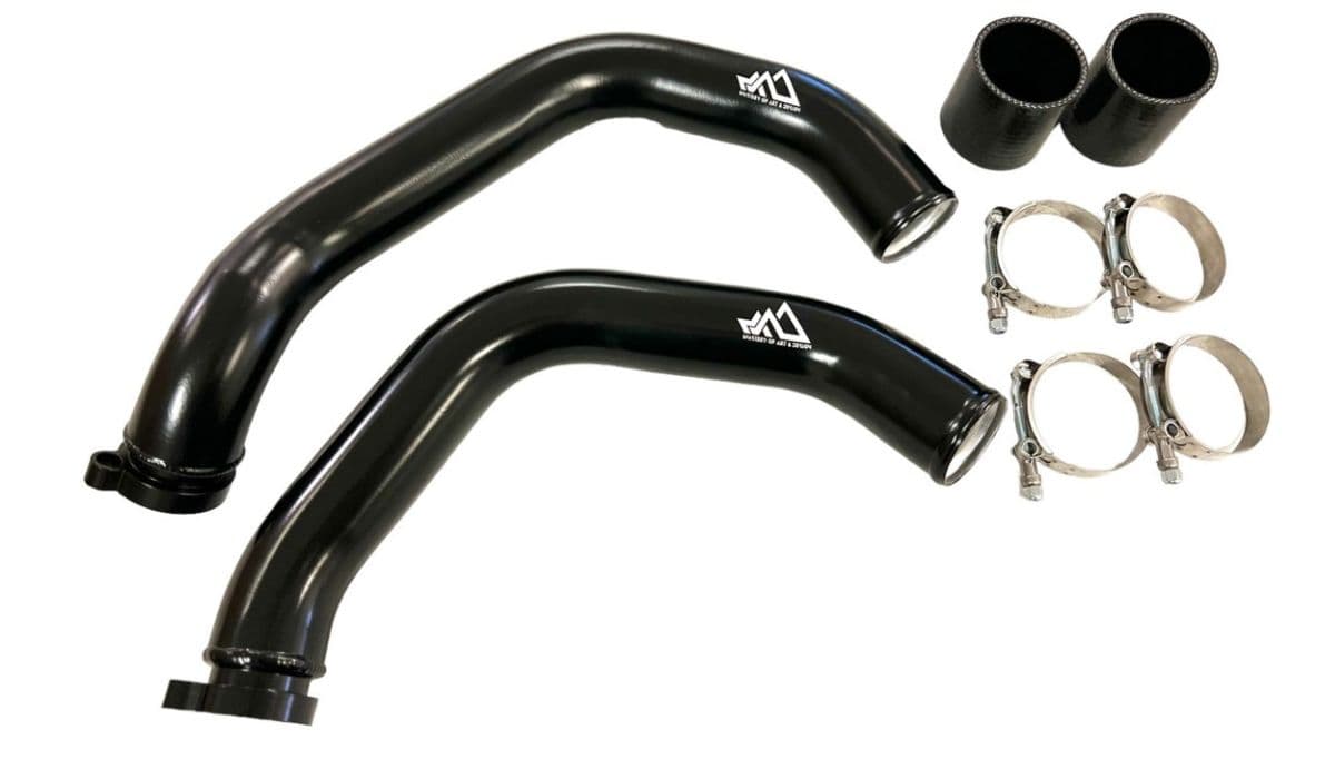
Permanent resolution requires transitioning to metal piping capable of sustaining 40+ psi without deformation. Aluminum kits dominate the market for balance of cost, weight, and durability—mandrel-bent tubing with CNC-machined billet flanges ensures precise fitment.
Reputable manufacturers include VRSF for budget-conscious black anodized sets with optional meth bungs, BMS for wrinkle black finishes proven on high-horsepower builds, AMS Performance for larger-diameter options minimizing flow restrictions, and ARM Motorsports for reinforced designs targeting 800+ whp applications. Silicone couplers and stainless T-bolt clamps accompany most kits. Essential tools encompass socket sets (8-13mm), extensions for tight access, Torx drivers, pliers for factory clamps, and trim tools for undertray removal.
Conducting Diagnostics to Pinpoint the Affected Section
Thorough verification guides part selection. Inspect hot-side pipes visually from above and below, focusing on turbo outlet transitions and intercooler inlets for cracks or oil residue from seepage.
Perform a boost leak test post-throttle body using a pressure rig to 25-30 psi—listen for escaping air or apply soapy water to reveal bubbles. Scan for overboost/underboost codes or log manifold pressure deviations. Temporary coupler tightening or zip-tie reinforcement tests containment, confirming pipe integrity as the root cause.
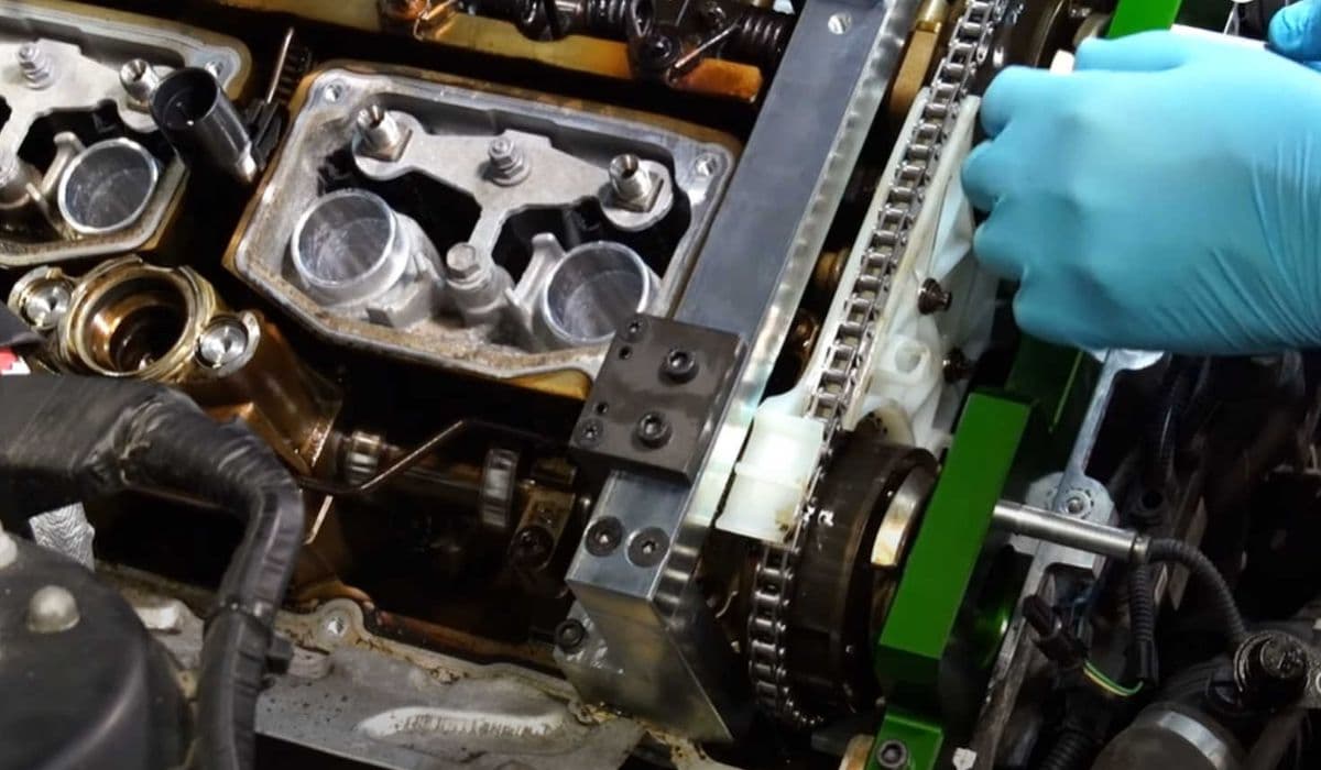
Step-by-Step Removal of Factory Charge Pipes
Secure the vehicle on stands with undertrays removed for underside clearance. Relieve residual pressure by loosening intercooler couplers gradually.
Disconnect throttle actuator linkages if obstructing access. Release factory spring-band or worm clamps, twisting pipes to break seals. Unbolt retaining brackets along routing paths. Extract hot-side sections downward after turbo flange separation—note orientations for reference during reinstallation. Minimal fluid loss occurs, but prepare absorbent materials.
Installing Aftermarket Charge Pipes with Secure Fitment
Degrease turbo outlets and intercooler ports completely. Align billet flanges meticulously to compressor housings, hand-starting fasteners.
Route new piping along OEM paths, avoiding contact with exhaust manifolds or moving components. Install reinforced silicone couplers fully over barbs, then torque T-bolt clamps progressively to 8-10 Nm for uniform compression. Verify clearances around heat shields and downpipes to prevent vibration-induced wear.
Verifying Integrity Through Post-Installation Testing
Reassemble panels and lower the vehicle. Clear any stored codes and adaptations via compatible scanner.
Warm the engine to operating temperature while monitoring idle stability. Conduct progressive road tests, logging boost hold across RPM ranges—consistent pressure without decay validates sealing. Multiple heat cycles allow couplers to seat fully, eliminating minor seeps.
Avoiding Common Installation Errors
Flange misalignment imposes undue stress, fostering future failures. Inadequate clamp torque permits coupler slippage under load.
Unsealed meth bungs introduce unmetered air if present. Overlooking turbo outlet O-ring condition risks persistent minor leaks. Improper routing leads to chafing against sharp edges over time.
Enhancing Boost System Durability for High-Output Builds
Long-term reliability integrates upgrades holistically. Complement charge pipes with upgraded intercoolers managing denser charge temperatures.
Incorporate high-flow diverter valves for precise pressure regulation. Regular inspections during oil changes catch early wear. Extreme tunes benefit from enlarged piping diameters reducing velocity losses. Maintain supporting modifications like robust engine mounts minimizing vibration transfer. These measures sustain consistent power delivery across aggressive calibrations.
More from BMW
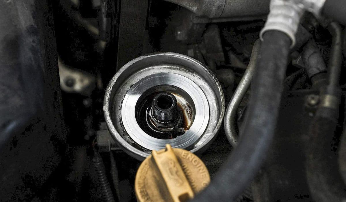
How to fix oil filter housing gasket (OFHG) leak
13.12.2025 12:13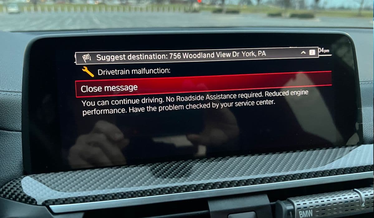
How to fix drivetrain malfunction error (2025 models)
13.12.2025 12:24
How to fix FRM footwell module lighting issues
13.12.2025 14:40
How to replace transfer case actuator (xDrive grinding noise)
13.12.2025 14:45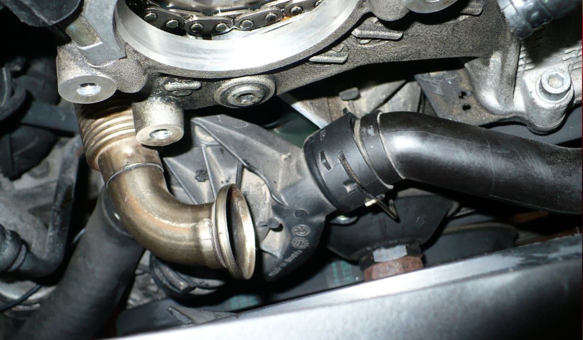
How to replace thermostat and coolant flange
13.12.2025 11:34